If you look at the above equations, you’ll find that there are three important geometric parameters to consider when sizing traces and PCB trace inductance. Controlling PCB Trace Inductance and Impedance

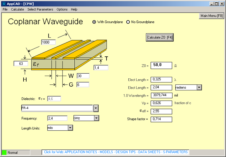
This need to minimize per-unit-length inductance is quite important, as the damping constant for any transient ringing signal (note that we’re not talking about reflections here) is inversely proportional to the PCB trace inductance. What I’ll do now is use the above equations to determine the correct w value that provides minimum trace inductance per unit length for a specified trace impedance value. Note that the above equation applies for single-ended surface microstrips that are isolated from all other signal traces. For now, I’ll confine the discussion to microstrips, but you can follow the process I’ll outline here for other trace geometries. Similar equations have been developed for symmetric striplines, embedded microstrips, coplanar waveguides, and offset/asymmetric striplines. Microstrip trace geometry, Waddell’s equations for microstrip impedance, and effective dielectric constant of microstrip traces You should use the more accurate Waddell's equations for determining the impedance of microstrip traces: or microstrip traces, the IPC 2142 formulas are only highly accurate within a particular impedance range. I’ve brought up this point in previous articles specifically for surface microstrips and symmetric stripline traces.
#PCB TRACE WIDTH CALCULATION HOW TO#
Let’s take a look at the basic formulas for sizing traces and how to keep impedance within your tolerance range.

However, when you need to control trace impedance and simultaneously reduce ringing, you need to carefully control the trace width to ensure transmission lines have desired impedance within some particular tolerance. Unlike many rules of thumb I’ve seen thrown about, this particular trace rule has some merit.

One particular rule for sizing traces is to always opt for wider traces when possible. Not all design rules are applicable in every situation, and they are often communicated without context.


 0 kommentar(er)
